
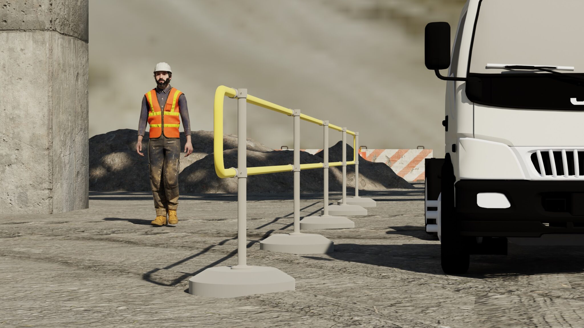
NON DRILL handrails can provide a practical way to delineate no-entry plant areas when permanent floor fixings are not available. At a Fortescue Metals site in Western Australia, the team needed to mark exclusion zones beneath conveyors and around operating plant. Many of the locations could not accept conventional handrail posts fixed into the ground. SafeSmart used non-drill handrail uprights with concrete base sections that included lifting points, then connected tube and fitting rails between the uprights. The resulting arrangement created a solid, relocatable boundary that the site could use across changing plant areas.
Project context and required task
The mining operation needed visible handrail delineation around areas that personnel were not permitted to enter. Restricted spaces included areas under conveyors and zones near operating plant. These were access control boundaries within a working facility, so the layout had to follow the equipment and leave normal site movement clear.
More structure than a light visual marker was required. Uprights and rails would define the restricted area, but the system still needed to move when the plant layout or exclusion zone changed.
Why fixed posts did not suit the work area
Many proposed locations did not provide a suitable way to fix conventional handrail posts into the floor. New holes or permanent anchors were therefore not part of the selected arrangement.
A fixed line would also have limited future relocation. Plant access requirements can move as work areas change, and the client wanted a system that could be used elsewhere on site. The design had to support a firm boundary while remaining recoverable.
The SafeSmart solution
SafeSmart proposed a project-specific arrangement using NON DRILL handrail uprights and concrete base sections. Each base included a lifting point. The upright connected to the base, and tube and fitting rails ran between the posts to form the handrail line.
This precast handrail method placed the support in the concrete base rather than relying on a new floor fixing at every location. It also retained familiar tube and fitting components for the rails, which let the boundary follow the required plant area.
How the precast handrail worked
Concrete base support
The concrete section formed a stable base for the upright. This addressed locations where the floor could not accept the planned handrail fixing and kept the support arrangement independent of the surrounding slab.
Lifting point for relocation
A lifting point was incorporated into the base section. That feature gave the site a defined way to handle the heavy base when the delineation line needed to move to another suitable area.
NON DRILL upright connection
The non-drill handrail upright connected to the concrete base and provided the post for the rail system. The project used the upright as part of this base-supported arrangement rather than fixing each post directly into the plant floor.
Tube and fitting rails
Tube and fitting rails joined the uprights to complete the delineation boundary. The component-based layout could be set out around the restricted zone and adjusted when a different length or direction was required.
Project delivery and coordination
The project outcome depended on matching each base location to the operating area. The handrail line had to be visible without blocking intended access routes or interfering with the plant it surrounded.
Relocation also needed planning. The lifting point provided a handling connection, but each move still required a suitable method, competent personnel and confirmation that the new location could support the base arrangement.
Outcomes for the client and crew
Delineation without new floor fixings
Concrete base sections allowed the handrail line to be established in areas where conventional post fixing was not available. The result addressed the site constraint without adding a direct fixing at each upright.
Relocation across plant areas
Built-in lifting points allowed the system to be moved using the site’s approved handling method. This supported the client’s aim to use the arrangement in different locations.
Clearer restricted area boundaries
Connected uprights and rails created a physical delineation line beneath conveyors and around operating plant. Personnel could see the boundary of the no-entry area from the normal approach.
Reusable component arrangement
Upright and tube components could be configured to suit another suitable zone. The handrail system could be reused across suitable areas on site, subject to review of the new position and duty.
The handrail duty must remain clear
This system was supplied for plant area delineation. A temporary safety railing used to mark an exclusion zone should not be represented as a temporary guardrail for fall protection unless the complete arrangement is separately designed, approved and installed for that duty.
Future users should confirm the intended function, rail loads, base stability and handling method before selecting a similar setup. Site traffic, wind exposure, floor capacity and interfaces with operating equipment also need project-specific review.
What other project teams can apply
When floor fixing is limited, start by defining whether the boundary is for delineation or fall protection. The answer changes the design basis and the evidence needed before use.
For a relocatable delineation system, review the proposed line, base support, lifting method and clearances around the plant. A precast handrail arrangement can then be assessed against the actual site duty rather than treated as a generic barrier.
Review a NON DRILL delineation method
Send SafeSmart the proposed exclusion zone, floor conditions, required rail layout and relocation method. The team can review whether a concrete base and non-drill handrail arrangement suits the intended plant area duty.

